Card Edge Connectors

Card Edge Connectors

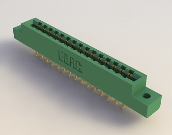
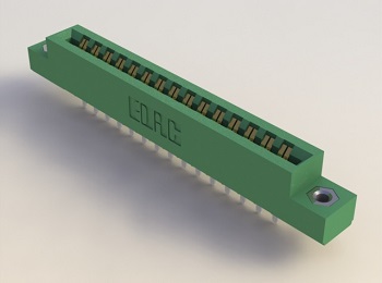
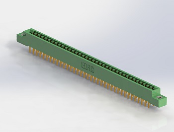
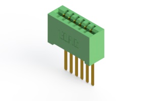
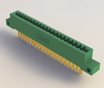
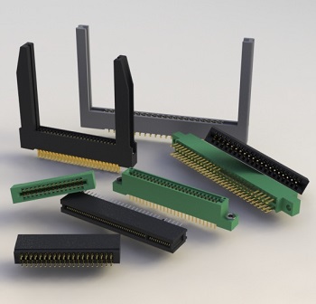
Card edge connectors available in a number of contact spacings, with multiple options for contact terminations, plating thicknesses and mounting styles.

Part type Description Total number
of contacts
Contact
spacing
Connector
mounting
pattern
Nominal
thickness
of PCB
Current
max.
[A]
Insulator
withstanding
voltage
min.
[V]
Contact
resistance
max.
[mΩ]
Insulation
resistance
min.
[MΩ]
Operating
temperature
[°C]
Enlarge using the cursor
100 Series
103 Series
105 Series
106 Series

 (328 kB)
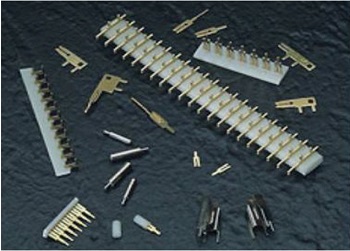
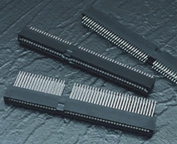
  • contacts for PCB on strips (0.100" or 0.200" contact spacing) or loose
  • other spacing available with loose contacts
  • various contact pattern and tail lenght
  • contact pattern on strips: 103 - horizontal, 105 - vertical, 106 - 45°
  • contact plating: gold over nickel for entire contacts
2 - 60 (0.200")
2 - 120 (0.100")
0.100" (2.54 mm) or
0.200" (5.08 mm)
(on strips)
  0.062" (1.57 mm)
or
0.125" (3.18 mm)
5, 10   10    
243 Series
 (438 kB)
  • 0.200" (5.08 mm) pitch
  • single or dual row configurations
  • high profile insulator body 0.656" (16.66 mm)
  • polarizing keys
  • contact termination: 0.045" (1.14 mm) square wire wrap, dual-row at 0.200" (5.08 mm) spacing
  • contact plating: gold over nickel for entire contacts
2, 3 (1 row)
4, 6 (2 rows)
0.200"
(5.08 mm)
0.200"
(5.08 mm)
x
0.200"
(5.08 mm)
0.062"
(1.57 mm)
5 1800 10 5000 -65 – +125
305 Series
315 Series
355 Series

 (273 kB)
  • 0.156" (3.96 mm) pitch
  • dual row configuration
  • low profile insulator body 0.470" (11.94 mm)
  • contact termination: PCB tail, wire hole and extender board bends
  • optional pre-assembled card guides
  • polarizing keys
  • contact plating: gold on the mating area, tin on the contact tails, nickel underplate
12 - 86
(2 rows)
0.156"
(3.96 mm)
0.156"
(3.96 mm)
x
0.140"
(3.56 mm)
0.062"
(1.57 mm)
5 1800 10 5000 -65 – +125
306 Series
316 Series
356 Series

 (496 kB)
  • 0.156" (3.96 mm) pitch
  • single centreline row
  • low profile insulator body 0.460" (11.68 mm)
  • contact termination: PCB tail, wire hole
  • optional pre-assembled card guides
  • polarizing keys
  • contact plating: gold on the mating area, tin on the contact tails, nickel underplate
6 - 43
(1 row)
0.156"
(3.96 mm)
0.156"
(3.96 mm)
0.062"
(1.57 mm)
5 1800 10 5000 -65 – +125
307 Series
357 Series

 (265 kB)
  • 0.156" (3.96 mm) pitch
  • single or dual row configurations
  • low profile insulator body 0.460" (11.68 mm)
  • contact termination: PCB tail (straight or right angle), wire hole, square wire wrap, and extender board bends
  • optional pre-assembled card guides
  • polarizing keys
  • contact plating: gold on the mating area, tin on the contact tails, nickel underplate
6 - 44 (1 row)
12 - 88 (2 rows)
0.156"
(3.96 mm)
0.156"
(3.96 mm)
x
0.200"
(5.08 mm)
0.062"
(1.57 mm)
5 1800 10 5000 -65 – +125
310 Series
 (725 kB)
  • 0.156" (3.96 mm) pitch
  • single or dual row configurations
  • low profile insulator body 0.460" (11.68 mm) with card slot barrier
  • contact termination: PCB tail, wire hole, square wire wrap and extender board bends
  • polarizing keys
  • contact plating: gold on the mating area, tin on the contact tails, nickel underplate
30 (1 row)
60 (2 rows)
0.156"
(3.96 mm)
0.156"
(3.96 mm)
x
0.200"
(5.08 mm)
0.062"
(1.57 mm)
5 1800 10 5000 -40 – +105
317 Series
 (261 kB)
  • 0.156" (3.96 mm) pitch
  • single or dual row configurations
  • high profile insulator body 0.720" (18.29 mm)
  • contact termination: 0.045" (1.14 mm) square wire wrap
  • optional pre-assembled card guides
  • polarizing keys
  • contact plating: gold over nickel for entire contacts
6 - 43 (1 row)
12 - 86 (2 rows)
0.156"
(3.96 mm)
0.156"
(3.96 mm)
x
0.200"
(5.08 mm)
0.062"
(1.57 mm)
5 1800 10 5000 -65 – +125
322 Series
 (218 kB)
  • 0.156" (3.96 mm) pitch
  • single or dual row configurations
  • low profile insulator body 0.473" (12.01 mm) with card guides
  • contact termination: PCB tail (straight or right angle), wire hole, square wire wrap, and extender board bends
  • polarizing keys
  • contact plating: gold on the mating area, tin on the contact tails, nickel underplate
22 (1 row)
44 (2 rows)
0.156"
(3.96 mm)
0.156"
(3.96 mm)
x
0.200"
(5.08 mm)
0.062"
(1.57 mm)
5 1800 10 5000 -40 – +105
325 Series
 (456 kB)
  • 0.100" (2.54 mm) pitch
  • single or dual row configurations
  • high profile insulator body 0.600" (15.24 mm)
  • contact termination: PCB tail, wire hole and 0.025" (0.64 mm) square wire wrap
  • polarizing keys
  • contact plating: gold on the mating area, tin on the contact tails, nickel underplate
5 - 61 (1 row)
10 - 122 (2 rows)
0.100"
(2.54 mm)
0.100"
(2.54 mm)
x
0.300"
(7.62 mm)
0.125"
(3.18 mm)
3 1200 10 5000 -65 – +125
333 Series
 (288 kB)
  • 0.156" (3.96 mm) pitch
  • single or dual row configurations
  • high profile insulator body 0.600" (15.24 mm)
  • contact termination: PCB tail (straight or right angle), wire hole, square wire wrap, and extender board bends
  • polarizing keys
  • contact plating: gold on the mating area, tin on the contact tails, nickel underplate
6 - 43 (1 row)
12 - 86 (2 rows)
0.156"
(3.96 mm)
0.156"
(3.96 mm)
x
0.200"
(5.08 mm)
0.062"
(1.57 mm)
3 1800 10 5000 -65 – +125
336 Series
 (262 kB)
  • 0.156" (3.96 mm) pitch
  • single or dual row configurations
  • high profile insulator body 0.720" (18.29 mm)
  • contact termination: wire wrap
  • polarizing keys
  • contact plating: gold on the mating area, tin on the contact tails, nickel underplate
6 - 43 (1 row)
12 - 86 (2 rows)
0.156"
(3.96 mm)
0.156"
(3.96 mm)
x
0.188"
(4.78 mm)
0.062"
(1.57 mm)
5 1800 10 5000 -65 – +125
337 Series
387 Series

 (309 kB)
  • 0.156" (3.96 mm) pitch
  • single or dual row configurations
  • high profile insulator body 0.600" (15.24 mm)
  • contact termination: PCB tail (straight or right angle), wire hole, square wire wrap, and extender board bends
  • optional pre-assembled card guides
  • polarizing keys
  • contact plating: gold on the mating area, tin on the contact tails, nickel underplate
6 - 43 (1 row)
12 - 86 (2 rows)
0.156"
(3.96 mm)
0.156"
(3.96 mm)
x
0.200"
(5.08 mm)
0.062"
(1.57 mm)
3 1800 10 5000 -65 – +125
338 Series
 (266 kB)
  • 0.156" (3.96 mm) pitch
  • single or dual row configurations
  • low profile insulator body 0.473" (12.01 mm)
  • contact termination: 0.045" (1.14 mm) square wire wrap
  • optional pre-assembled card guides
  • polarizing keys
  • contact plating: gold on the mating area, tin on the contact tails, nickel underplate
10 - 28 (1 row)
20 - 56 (2 rows)
0.156"
(3.96 mm)
0.156"
(3.96 mm)
x
0.200"
(5.08 mm)
0.062"
(1.57 mm)
5 1800 10 5000 -65 – +125
341 Series
391 Series

 (560 kB)
  • 0.100" (2.54 mm) pitch
  • single or dual row configurations
  • low profile insulator body 0.437" (11.10 mm)
  • contact termination: PCB tail, wire hole, and extender board bends
  • polarizing keys
  • contact plating: gold on the mating area, tin on the contact tails, nickel underplate
5 - 60 (1 row)
10 - 120 (2 rows)
0.100"
(2.54 mm)
0.100"
(2.54 mm)
x
0.140"
(3.56 mm)
0.062"
(1.57 mm)
3 1200 10 5000 -65 – +125
342 Series
392 Series

 (291 kB)
  • 0.100" (2.54 mm) pitch
  • single or dual row configurations
  • low profile insulator body 0.590" (14.99 mm)
  • contact termination: PCB tail, wire hole, square wire wrap, and extender board bends
  • polarizing keys
  • contact plating: gold on the mating area, tin on the contact tails, nickel underplate
5 - 60 (1 row)
10 - 120 (2 rows)
0.100"
(2.54 mm)
0.100"
(2.54 mm)
x
0.200"
(5.08 mm)
0.062"
(1.57 mm)
3 1200 10 5000 -65 – +125
345 Series
395 Series

 (295 kB)
  • 0.100" (2.54 mm) pitch
  • single or dual row configurations
  • high profile insulator body 0.600" (15.24 mm)
  • contact termination: PCB tail (straight or right angle), wire hole, square wire wrap, and extender board bends
  • optional pre-assembled card guides
  • polarizing keys
  • contact plating: gold on the mating area, tin on the contact tails, nickel underplate
5 - 72 (1 row)
10 - 144 (2 rows)
0.100"
(2.54 mm)
0.100"
(2.54 mm)
x
0.200"
(5.08 mm)
0.062"
(1.57 mm)
3 1200 10 5000 -65 – +125
346 Series
396 Series

 (293 kB)
  • 0.125" (3.18 mm) pitch
  • single or dual row configurations
  • high profile insulator body 0.600" (15.24 mm)
  • contact termination: PCB tail (straight or right angle), wire hole, square wire wrap, and extender board bends
  • optional pre-assembled card guides
  • polarizing keys
  • contact plating: gold on the mating area, tin on the contact tails, nickel underplate
5 - 50 (1 row)
10 - 100 (2 rows)
0.125"
(3.18 mm)
0.125"
(3.18 mm)
x
0.250"
(6.35 mm)
0.062"
(1.57 mm)
3 1500 10 5000 -65 – +125
368 Series
 (363 kB)
  • 0.156" (3.96 mm) pitch
  • dual row configurations
  • high profile insulator body 0.630" (16.00 mm)
  • contact termination: press fit option include 0.031" (0.79 mm) square wire wrap & PCB tails
  • polarizing keys
  • contact plating: gold over nickel for entire contacts
4 (end module)
6 (centre modul)
0.156"
(3.96 mm)
0.156"
(3.96 mm)
x
0.200"
(5.08 mm)
0.062"
(1.57 mm)
5 1800 10 5000 -40 – +125
379 Series
 (280 kB)
  • 0.150" (3.81 mm) pitch
  • single or dual row configurations
  • high profile insulator body 0.600" (15.24 mm)
  • contact termination: PCB tail, wire wrap and extender board bends
  • polarizing keys
  • contact plating: gold on the mating area, tin on the contact tails, nickel underplate
6 - 32 (1 row)
12 - 64 (2 rows)
0.150"
(3.81 mm)
0.150"
(3.81 mm)
x
0.200"
(5.08 mm)
0.062"
(1.57 mm)
3 1800 10 5000 -65 – +125
395-ISA Series
 (252 kB)
  • 0.100" (2.54 mm) pitch
  • for IBM-AT industry standard architecture
  • dual row configurations
  • high profile insulator body 0.600" (15.24 mm)
  • contact termination: PCB tail (straight or right angle), square wire wrap, and extender board bends
  • contact plating: gold on the mating area, tin on the contact tails, nickel underplate
98 (2 groups of contacts: 62 + 36) 0.100"
(2.54 mm)
0.100"
(2.54 mm)
x
0.200"
(5.08 mm)
0.062"
(1.57 mm)
3 1200 10 5000 -40 – +105
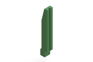
Card Guides
  • guides for Card Edge Connectors with 0.156" (3.96 mm) diameter mounting holes

Available versions: Card Guides
      0.062"
(1.57 mm)
        -65 – +125
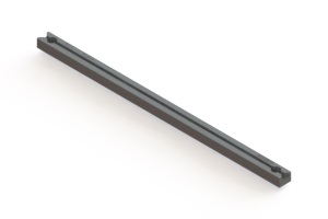
Uni-Guides
  • universal guides which provide PCB to connector alignment
  • variety of sizes
  • easy installation using 0.093" (2.36 mm) diameter eyelets or pop rivets or two sided tape

Available versions: Uni-Guides
             
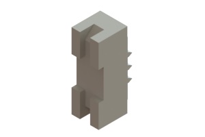
Polarizing Keys
  • polarizing keys for Card Edge Connectors
  • the shape adapted to the type of connector

Available versions: Polarizing Keys